Features:
Size 3" BSPT
Body Ductile Iron
Pressure Range 0.1 to 8 Bar
Temperature 0°C to 180°C
| Application | Steam Condensate |
|---|---|
| Driving Fluid | Steam or Air |
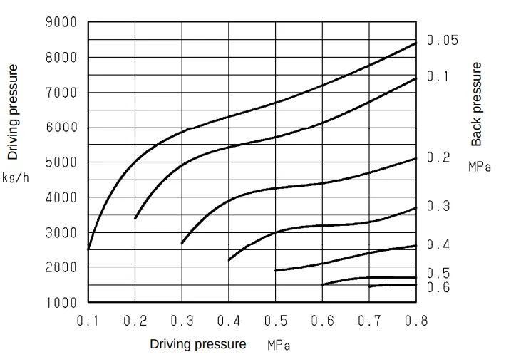
| Max Driving Pressure | 8 Bar (optimal is 1 to 2 Bar higher than back pressure) |
| Max Working Temperature | 180°C |
| Body | Ductile Cast Iron |
| Trim Parts | Stainless Steel |
| Float | Stainless Steel |


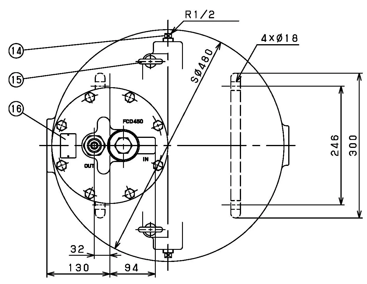
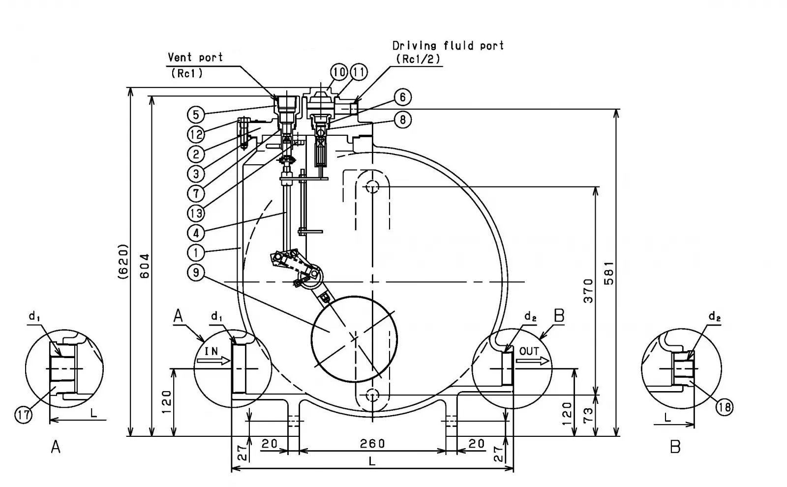
| Size | d1 | d2 | L | Weight (kg) |
|---|---|---|---|---|
| 80A | 3" BSPT | 2" BSPT | 500 | 90 |
All dimensions in mm unless specified otherwise

| Item | Description | Material | Qty |
|---|---|---|---|
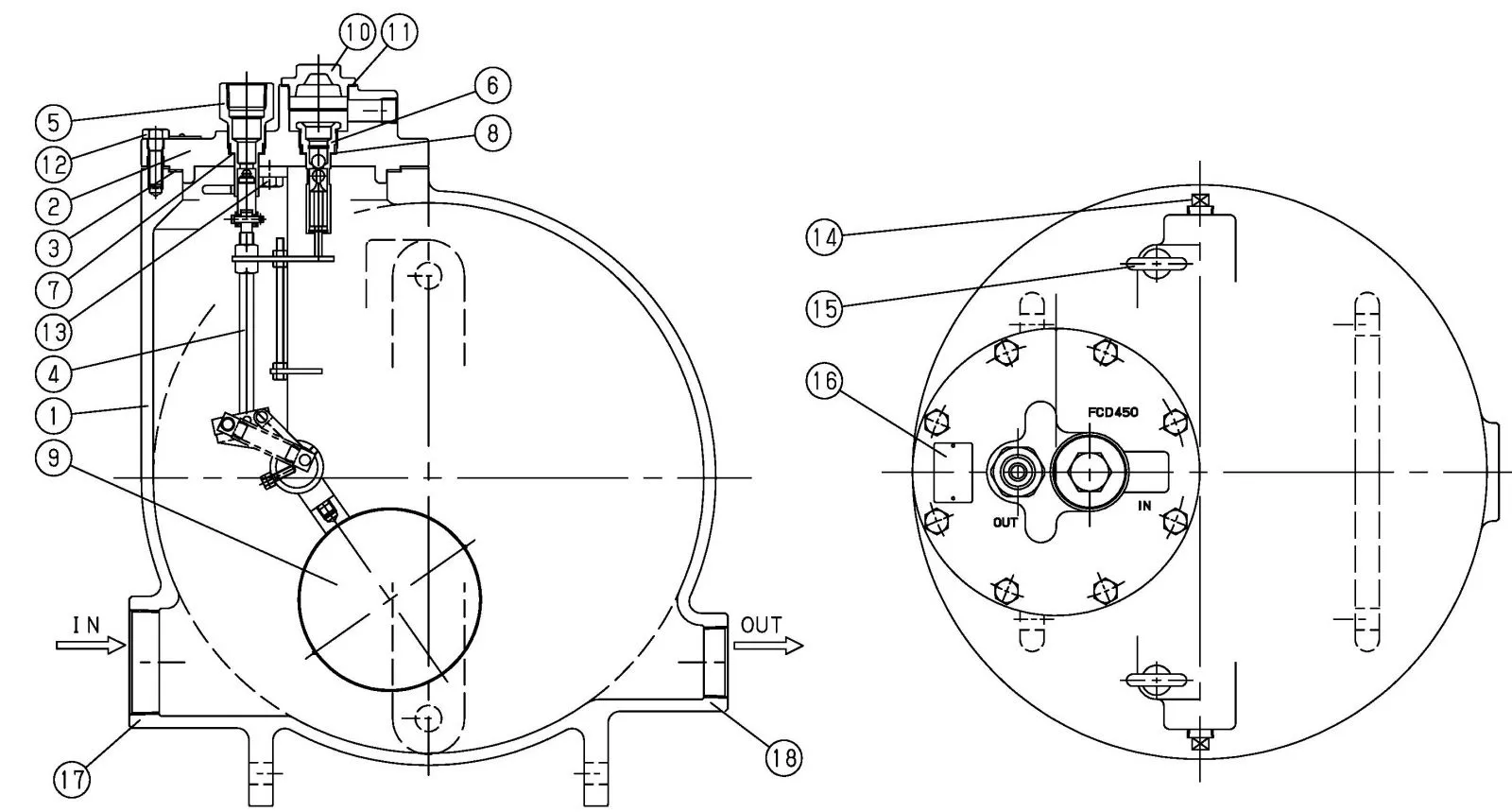
| 1 | Body | Ductile Cast Iron | 1 |
| 2 | Cover | Ductile Cast Iron | 1 |
| 3 | Gasket | Non Asbestos | 1 |
| 4 | Vent Valve P | Stainless Steel | 1 Set |
| 5 | Vent Valve Seat | Stainless Steel | 1 |
| 6 | Inlet Valve P | Stainless Steel | 1 Set |
| 7 | Gasket | Copper | 1 |
| 8 | Gasket | Copper | 1 |
| 9 | Float | Stainless Steel | 1 |
| Item | Description | Material | Qty |
|---|---|---|---|
| 10 | Cap | Ductile Cast Iron | 1 |
| 11 | Gasket | Non Asbestos | 1 |
| 12 | Bolt | Carbon Steel | 8 |
| 13 | Bolt | Stainless Steel | 2 |
| 14 | Plug | Stainless Steel or Cast Stainless Steel | 4 |
| 15 | Bolt | Carbon Steel | 2 |
| 16 | Name Plate | Aluminium | 1 |
| 17 | Bush | Malleable Cast Iron | 1 |
| 18 | Bush | Malleable Cast Iron | 1 |
Size 3" BSPT
Body Ductile Iron
Pressure Range 0.1 to 8 Bar
Temperature 0°C to 180°C
What is a Pumping Trap?
A pump trap is a self-contained mechanical pump designed for condensate recovery, most suitable for use in open vented condensate recovery applications. They can pump high temperature condensate/fluids without any cavitational issues that may be caused due to high temperatures. They can also be used to pump other industrial fluids. They normally use steam or compressed air as their motive power. They have no electric pumps or electric level controls, making them ideal for hazardous areas.
How does a Pumping Trap work?
Mechanical pump type traps have many names depending on the manufacturer. However they are in general, all designed to collect and recover hot clean condensate. Utilising the motive pressure of steam or compressed air, they are used to lift liquids such as hot clean condensate to a higher level. They are typically installed in conjunction with an atmospheric vented receiver, as an ‘open’ system, this vent is designed/sized to ensure any flash steam is vented to the atmosphere and to ensure no build up of pressure. Condensate is normally collected from multiple steam traps at the same time, discharging into the vented receiver and then it is usually pumped back to the boiler feedwater tank. Depending on the pump type/size, they can pump large quantities of condensate at a constant and steady rate. They come in a variety of sizes and shapes. However for the larger capacity units it is not uncommon to have a common body size with minor adjustments to inlet and outlet ports to manage the required capacity within a specific range. Size and type is determined by the installation, the amount of fluid to be pumped, the lift or total back pressure against the discharge port and the motive pressure available. Being a displacement type pump they have a cyclic pumping action. The pump body has a condensate inlet port and a discharge port fitted with check valves on each, to control the suction and discharge part of the process. The pump is also fitted with a motive inlet port and an exhaust port. The internals of the pump are fitted with a motive steam/air inlet valve, an exhaust valve and a float level control assembly. As hot condensate flows from the vented receiver vessel, into the pump via the inlet port and starts to fill the inside of the pump body. Condensate quickly builds up and starts to reach the level of the float.The float becomes buoyant and the float mechanism which is attached to the steam inlet valve and exhaust valve will start to rise. Note; at this point the steam inlet valve is in the closed position and the exhaust valve is open. With the level of condensate getting higher, the float will continue to move upward causing the attached mechanism to open the motive steam/air inlet valve and close the exhaust valve. As the motive steam/air enters the pump body, it pressurises the body causing the inlet check valve to close and the discharge check valve to open, allowing the accumulated condensate to be discharged out under the force of the motive pressure, into the pumped return line, allowing the condensate to be moved to another location and or elevated to a higher level. As the condensate leaves the pump body the float will start to drop, allowing the attached mechanism to close the motive inlet port and open the exhaust port so as to exhaust any excess pressure in the pump body, causing the cycle to start over. With each cycle a measure of condensate/fluid is pushed into the downstream pipework.
How long will my Pump Trap last?
This really depends upon the environment and the quality of your pumped condensate/fluid, and the steam that the pump trap operates with. The installation of a strainers on the steam inlet is highly recommended to reduce the amount of dirt and other impurities from entering the steam inlet valve seat. A correctly selected and sized Pump Trap with a good maintenance regime, should perform for many years. Obviously it must be installed in accordance with the manufacturer's recommendations and it is highly recommended that regular inspection of the Pump Trap is carried out at least once a year and if found to be faulty it should be cleaned and or repaired as required. This will give the pump the best opportunity to continually operate satisfactorily for many years. When a pump trap does fail it can lead to a loss of production and or a waste of energy through leaking steam, hot clean condensate can overflow down the drain, fuel costs will increase.
How do I install a Pump Trap?
It is vitally important when selecting and sizing any type of pump trap, that certain criteria is met. Such as the operating pressure/temperature, the duty required, the application, back pressure etc. It must be selected to suit the application. Pump Traps should always be installed in accordance with the manufacturers recommendations and in accordance with good steam fitting practice. It is highly recommended that they are purchased as a plug and play skid package, with all the necessary ancillaries already attached, this will help to avoid any inefficiencies in your system operation. Always insure; correct direction of flow, correct orientation & leave clear access for general maintenance and repairs.They can have various end connections such as flanged, threaded, etc so installation will need to take this into account. Always take into consideration the discharge of the vent to the atmosphere, ensure it is discharging to a safe place, not to cause noise issues, damage to the environment or injury to animals and humans. A correctly designed receiver will have an overflow built in ready for connection to drain by the installer. This is incase of any pump failure. Ensure a water seal is installed in the drainline to avoid flash steam bypass during normal operation. Most pumps will have a max motive steam pressure allowable. Do not exceed this pressure. The most appropriate value of driving pressure is the back pressure at outlet side + 100 to 200 kPa. We can provide assistance with the sizing, selection of pump traps and also assist with suggestions for a suitable installation.
What are typical uses of a Pump Trap?
When saturated steam gives up its energy to any colder surface it condenses and condensate is formed. This condensate is usually a hindrance to heat transfer efficiency and a potential danger to the safe operation of any steam system in general. It is important that those charged with designing, operating and maintaining a steam and condensate system are also familiar with steam and condensate system design and good steam fitting practice. In particular condensate recovery is not always given the attention it deserves. The results of poor design and installation can be measured in dollars and cents. Returning the highest possible amount of condensate back to the boiler provides a significant return on investment as it will go towards reducing energy, chemical and maintenance costs. Also as condensate is clean distilled water that contains virtually no total dissolved solids, returning condensate to the feed water tank will also reduce the amount of blowdown required from the boiler. This reduces the amount of energy lost through unnecessary boiler blowdown. Pumping high temperature condensate without cavitation or electrical problems allows maximum heat energy recovery. A Pumping Trap's main use is usually to be installed as an integral part of any vented condensate recovery system. Typically they are installed at low points in the system. Where condensate being discharged from multiple steam traps can fall by gravity, unaffected by backpressure, to be collected in the vented receiver, and when sufficient quantities are available the Pumping Trap will pump the condensate back to the boiler feedwater tank, which is usually some distance away and or at an elevated location. If the distance is too far and or too elevated for the one pump they can be installed in series at different locations, to pump from one to another unit closer to the destination, which then pumps to the desired end location. If the required duty is greater than any one Pumping Trap they can be coupled together in groups of two or three or as required to achieve a desired result. Skid mounted package units are generally available.
How long will my product take to get to me?
With a standard stocked bare Pumping trap, it depends upon where you are based and the freight method chosen. If the express freight option is selected it is usually next day delivery to metropolitan areas in Australia for under 5kg. If free freight has been selected it will go by road freight which can be anywhere from 1 to 10 days depending upon your location. It usually averages 3 days. However if a skid package is ordered, delivery will depend on fabrication times as these units are fabricated to order. With the pump and ancillaries in stock, the average time for a standard package is approx 4-6weeks.
What warranty do I get?
All of our products come standard with a 12 month warranty. The good news is we have very strict quality controls and all valves leave our warehouse after being tested and inspected during manufacture and assembly. so there are rarely any issues.

Size 3" BSPT
Body Ductile Iron
Pressure Range 0.1 to 8 Bar
Temperature 0°C to 180°C

| Application | Steam Condensate |
|---|---|
| Driving Fluid | Steam or Air |
| Max Driving Pressure | 8 Bar (optimal is 1 to 2 Bar higher than back pressure) |
| Max Working Temperature | 180°C |
| Body | Ductile Cast Iron |
| Trim Parts | Stainless Steel |
| Float | Stainless Steel |


| Size | d1 | d2 | L | Weight (kg) |
|---|---|---|---|---|
| 80A | 3" BSPT | 2" BSPT | 500 | 90 |
All dimensions in mm unless specified otherwise

| Item | Description | Material | Qty |
|---|---|---|---|
| 1 | Body | Ductile Cast Iron | 1 |
| 2 | Cover | Ductile Cast Iron | 1 |
| 3 | Gasket | Non Asbestos | 1 |
| 4 | Vent Valve P | Stainless Steel | 1 Set |
| 5 | Vent Valve Seat | Stainless Steel | 1 |
| 6 | Inlet Valve P | Stainless Steel | 1 Set |
| 7 | Gasket | Copper | 1 |
| 8 | Gasket | Copper | 1 |
| 9 | Float | Stainless Steel | 1 |
| Item | Description | Material | Qty |
|---|---|---|---|
| 10 | Cap | Ductile Cast Iron | 1 |
| 11 | Gasket | Non Asbestos | 1 |
| 12 | Bolt | Carbon Steel | 8 |
| 13 | Bolt | Stainless Steel | 2 |
| 14 | Plug | Stainless Steel or Cast Stainless Steel | 4 |
| 15 | Bolt | Carbon Steel | 2 |
| 16 | Name Plate | Aluminium | 1 |
| 17 | Bush | Malleable Cast Iron | 1 |
| 18 | Bush | Malleable Cast Iron | 1 |