Valve Terminology
Below is a guide to the Valve Terminologies used across our range of products from Ball Valves, Solenoids, Actuators & Ancillary Products.
Solenoid Valve Terminology
- 2 way is a two port valve that turns the flow on or off.
- 3 way is a three port valve that allows flow through the valve into a chamber, and then out through the valve exhaust. The universal function can also be used as a diverter valve.
- 5/2 way is a five port, two position valve that will put a fluid or air into one end of a double acting device as well as allowing the other end vent to exhaust.
- Zero Differential are solenoid valves that can operate under zero head pressure (do not need a differential pressure drop across the valve to work). This is made up of two categories, direct acting and coupled diaphragm.
- Direct acting are solenoid valves that are activated purely by the electromagnetic forces in the valve and do not rely on the fluid pressure to assist. Hence they are used where little or no fluid pressure is available such as vacuum service or low pressure applications.
- Differential operated are solenoid valves that do rely on the fluid pressure to assist in activating the valve. This helps in developing valves with larger orifices, higher pressures and smaller coils.
- Normally closed (N.C.) means that when the solenoid valve is not energised the supply pressure port is closed off. In the case of 3 way valves the downstream port is open to the exhaust port.
- Normally open (N.O.) means that when the solenoid valve is not energised the supply pressure port is open to the downstream port. In the case of 3 way valves the downstream port is closed to the exhaust port.
- IP rating is an international standard to denote the degree of protection against water and solid objects. All of our electrical coils with DIN plugs have an IP65 rating. The '6' denotes a complete protection against items as small as dust and '5' is protection against low pressure jets of water from all directions.
- Flame proof relates to the electrical part of a solenoid valve only (usually the coil and operator assembly) and is a way of making the valve safe to use in an explosive atmosphere. These valves must be installed in compliance to the wiring standards for this type of approval and in a zone compatible to the approved code and temperature rating.
- D.I.P rating relates to Dust and Ignition Proof
- N.B. Bar relates to pressure: 1 Bar = 14.7psi = 100KPA = 1 atmosphere.
Ball Valve Terminology
Components of 2 Way Valves
- 2 piece - Body manufactured from two castings and threaded together.
Advantage: Lower cost
Disadvantage: Difficult to remove from the pipe work, usually non-replaceable - 3 piece - Body manufactured from three castings and clamped with tie rods.
Advantage: Able to be removed from the pipework without disruption, repairable, usually a higher spec valve
Disadvantage: Usually more expensive
Components of 3 Way Valves
- 4 piece - Body manufactured from four castings and threaded together (or bolted together in the case of flanged 3 way valves)
Function of 2 way / 2 position Valves
- Two port valve that turns the flow ON or OFF
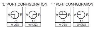
Function of 3 way / 2 position Valves
Three port valve that is available in two different flow configurations:
- L-Port - Commonly used as a flow diverter. In one position Port C is connected to Port A, and in the second position Port C is connected to Port B.
- T-Port - Commonly used as a valve for draining or relieving the downstream pressure. In one position Port C is connected to Port A, and in the second position Port A is connected to Port B.
Actuator Terminology
Pneumatic
- Double Acting (DA) - Pnuematic actuator that requires an air signal to turn it ON and a second signal to turn in OFF.
- Spring Return (SR) - Pneumatic actuator with spring return that requires an air signal to actuate - Spring to Close (Also known as Single Acting). The advantage of this actuator is that it only requires a single air signal to operate and is fail safe in the event of a power failure.
Electric
- A motorised gearbox drives the valve. Commonly used where compressed air is not available. Slower operation - usually 12 to 15 seconds depending on the size of the actuator and valve.
- Commonly as standard are an ON/OFF operation where a power signal is required to both open and close the actuator.
- Available as Modulating Control (4~20mA Input for position control) & Spring Return
Pressure / Vacuum Switches
- Single Pole Double Throw (SPDT) - With this type of switch the electrical circuit can be "made" when the switch is activated (common to N.O.) or "broken" when the switch is activated (common to N.C.).
- Single Pole Single Throw (SPST) Normally Closed - With this type of switch the electrical circuit will be "broken" when the switch is activated.
- Single Pole Single Throw (SPST) Normally Open - With this type of switch the electrical circuit will be "made" when the switch is activated.
- Deadband / Hysterisis / Differential - are all terms used to describe the difference between when a switch activates and when it resets. Because of the mechanics of the micro-switch this is seldom at the same setting. Some of our switches have fixed deadbands (Series PMM, VCM) and others have limited adjustable deadbands (Series PSM, PSP, VSM, adjustable up to 30% of full scale).
- Set Point is the setting at which the switch will activate.
- Rising Set Point - Switch will activate as pressure rises to set pressure
- Falling Set Point - Switch will activate as pressure falls to set pressure
Measurements of Flow / Flow Coefficients
Qn - Pneumatic flow of valve in litres of air per minute at 20°C and input pressure of 6 Bar (600 kPa) with a pressure drop of 1 Bar (100 kPa)
Cv - Imperial measurement of flow across a valve in US Gallons per minute of Water at 60°F with a pressure drop of 1 PSI across the valve.
Kv - Metric measurement of flow across a valve in m3 per hour of Water at a temperature between 5°C & 40°C with a pressure drop of 1 Bar (100 kPa) across the valve
Flow through a valve for both Fluids and Gases can be calculated by using the below formulas.
| Fluids | Gases |
|---|---|
| Q = 14.28cv √?P/r where, Q = Flow (L/min) ?P = Pressure Drop r = Density of Fluid (kg/dm^3) (water = 1kg/dm^3) cv = Flow rating of valve |
Q = 400cv √(P2 + 1.013) x ?P x √273/273+t where, P2 = Outlet Pressure ?P = Pressure Drop t = Gases Temperature cv = Flow Rating of Valve |
Working out Amps / Volts or Watts
![]()
![]()
Duty Cycle - Compliance to IEC Standard
Duty cycle means the starting frequency. The formula for calculating the Duty Cycle and the Rest Time is as follows,
![]()
![]()
For Example, the running time for an 0M-2 Actuator is 15 seconds.
- At 30% Duty Cycle → 15 x (1-30%) / 30% = 35 seconds Rest Time
- At 75% Duty Cycle → 15 x (1-75%) / 75% = 5 seconds Rest Time
The higher the Duty Cycle rating, the shorter the rest time between cycles is.


