Features:
Mounting Interface F05 to F16
Drive Size 7mm to 46mm
Body 2205 Duplex Stainless Steel
Function Valve Lockout
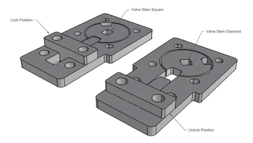
These patented valve safety lockouts are made from 2205 duplex stainless steel and are designed to sit between a valve and actuator (pneumatic, electric or gear box). The lockout is achieved by directly engaging to the spindle of the valve achieving the highest safety standard possible. These are used extensively in critical safety applications such as sugar mills and refineries. The unit is strong, simple to operate and compact.


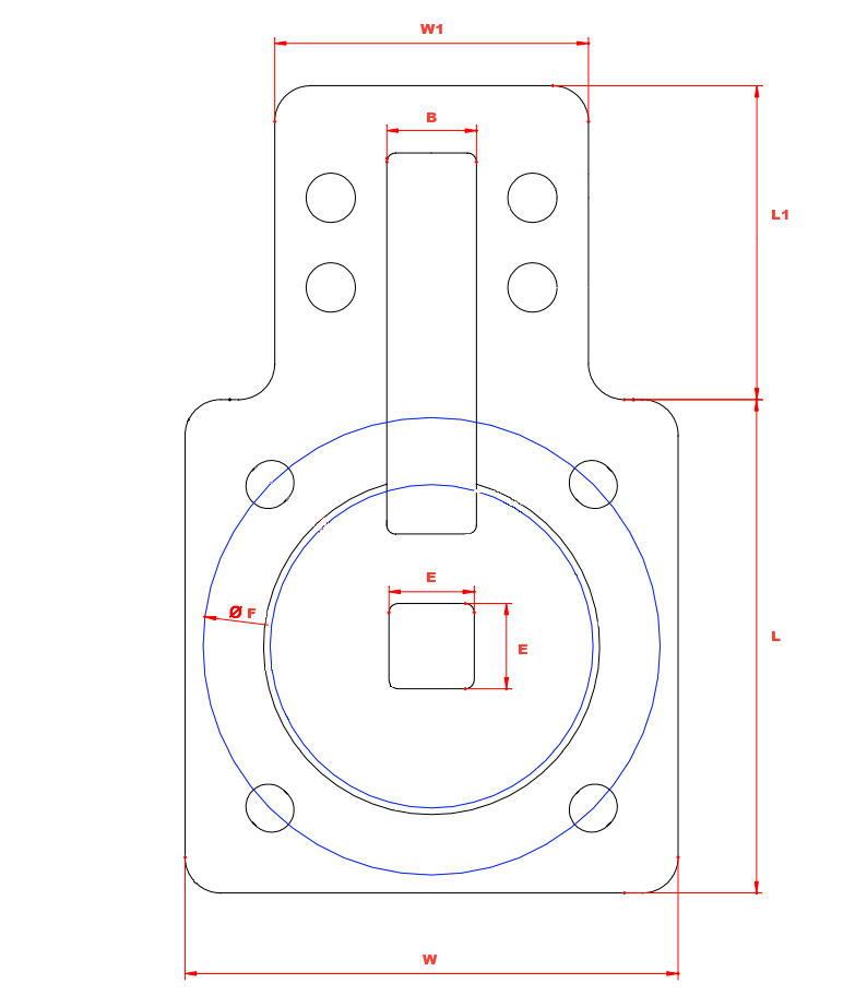
| Model | W | W1 | L | L1 | B | E | F |
|---|---|---|---|---|---|---|---|
| VSLF05-07 | 7 | F05 | |||||
| VSLF07-11 | 80 | 65 | 80 | 65 | 15 | 11 | F07 |
| VSLF07-14 | 80 | 65 | 80 | 65 | 15 | 14 | F07 |
| VSLF10-19 | 110 | 70 | 110 | 70 | 20 | 19 | F10 |
| VSLF10-22 | 110 | 70 | 110 | 70 | 20 | 22 | F10 |
| VSLF12-22 | 140 | 90 | 140 | 90 | 25 | 22 | F12 |
| VSLF12-27 | 140 | 90 | 140 | 90 | 25 | 27 | F12 |
| VSLF14-36 | 160 | 100 | 160 | 100 | 30 | 36 | F14 |
| VSLF16-46 | 200 | 110 | 200 | 110 | 30 | 46 | F16 |
All dimensions in mm unless shown otherwise.
Mounting Interface F05 to F16
Drive Size 7mm to 46mm
Body 2205 Duplex Stainless Steel
Function Valve Lockout
What is a Valve Safety Lockout?
A Valve Safety Lockout does exactly what the name describes; it locks out the operation of a valve so that it protects the user against accidental actuation of the valve. This is commonly used in maintenance periods where it is critical for safety that the valve not be operated while work is being conducted.
How does a Valve Safety Lockout work?
The lockout works by a puck and disc being mounted between the valve and actuator. The puck is directly connected to the shaft of the valve and has a keyway in it which a tongue can be pressed into when the user wants the valve to be locked out. Even if the valve is actuated the tongue stops the puck rotating which therefore does not allow the valve shaft to move. This achieves a mechanical lockout of the valve.
How long will my Valve Safety Lockout last?
These are made of pressure die cast 2205 Duplex stainless steel so will outlast the life of your valve and actuator.
How do I install a Valve Safety Lockout?
The lockout is installed directly between the valve and actuator (pneumatic, electric or gear box). The drive and mounting bolts for the actuator/valve pass directly through the lockout. The internal puck is put directly over the stem of the valve and then the valve and actuator are mounted.
What are typical uses of Valve Safety Lockout?
These safety lockouts are used in critical areas where the valve must have a safety lock out mechanism. This is very common in industries such as sugar mills and refineries but can be used in any application.
How long will my product take to get to me?
This depends upon where you are based and the freight method chosen. If the express freight option is selected it is usually next day delivery to metropolitan areas in Australia for under 5kg. If free freight has been selected it will go by road freight which can be anywhere from 1 to 10 days depending upon your location. It usually averages 3 days.
What warranty do I get?
All of our products come standard with a 12 month warranty. The good news is we have very strict quality controls and all product leaves our warehouse tested and inspected so there are rarely any issues. These all come with full material and testing certifications should they be required.

Mounting Interface F05 to F16
Drive Size 7mm to 46mm
Body 2205 Duplex Stainless Steel
Function Valve Lockout

These patented valve safety lockouts are made from 2205 duplex stainless steel and are designed to sit between a valve and actuator (pneumatic, electric or gear box). The lockout is achieved by directly engaging to the spindle of the valve achieving the highest safety standard possible. These are used extensively in critical safety applications such as sugar mills and refineries. The unit is strong, simple to operate and compact.


| Model | W | W1 | L | L1 | B | E | F |
|---|---|---|---|---|---|---|---|
| VSLF05-07 | 7 | F05 | |||||
| VSLF07-11 | 80 | 65 | 80 | 65 | 15 | 11 | F07 |
| VSLF07-14 | 80 | 65 | 80 | 65 | 15 | 14 | F07 |
| VSLF10-19 | 110 | 70 | 110 | 70 | 20 | 19 | F10 |
| VSLF10-22 | 110 | 70 | 110 | 70 | 20 | 22 | F10 |
| VSLF12-22 | 140 | 90 | 140 | 90 | 25 | 22 | F12 |
| VSLF12-27 | 140 | 90 | 140 | 90 | 25 | 27 | F12 |
| VSLF14-36 | 160 | 100 | 160 | 100 | 30 | 36 | F14 |
| VSLF16-46 | 200 | 110 | 200 | 110 | 30 | 46 | F16 |
All dimensions in mm unless shown otherwise.